Development of equipment and methods for ultrasonic inspection of rotary kiln bandages
Rotary kilns are used for the production of cement and the firing of raw materials in the metallurgical and chemical industries. The length of modern furnaces can reach 250 m, and a diameter of 6 meters or more.
The most heavily loaded and potentially dangerous parts of rotating furnaces are support bands of solid rectangular cross-section, put on the furnace body with a certain radial clearance, as well as bands of solid curly cross-section, welded into the furnace body. The thickness of the bandages can be 500 mm or more with a width along the axis of the furnace from 700 mm to 1300 mm.
Operational experience indicates that prolonged unplanned downtime of rotating furnaces is associated with the identification and elimination of transverse cracks in the bandages. This is how the case of detecting and eliminating a crack on the bandage of a rotating furnace at the Heidelberg Cement plant in the Tula region is described. It is reported that ultrasonic inspection when the furnace was stopped revealed a crack that did not come to the surface, the size of which would require the use of 45 kg of welding materials to eliminate it. After a month of operation of the furnace, the crack increased in size and came to the surface, repairs required 588 kg of welding materials and 19 days of work on welding the crack.
These features make it relevant to develop and apply ultrasonic inspection of the bandage during operation of the rotary kiln in order to timely identify possible defects and plan work to eliminate them.
The rotation of the furnace allows scanning with an ultrasonic sensor on the outer surface of the bandage, but requires a special approach. It is necessary to carry out monitoring at a rotation speed of about 1 m / s, a bandage surface temperature of 120 ° C-150 ° C, to provide a spatial aperture of the scan of about 500 mm for an input angle of 0 ° on longitudinal waves and about 800 mm at an input angle of 45 ° on transverse waves.
The high speed of movement of the transducer relative to the part limits the number of radiation and reception cycles per step of movement of the transducer, and the presence of noise and a large sound aperture requires averaging of signals to reduce noise levels. The requirement to ensure averaging at a large scanning step is solved by using the CFA-2D acoustic imaging technology developed by ECHOPLUS Company, which allows you to obtain a detailed acoustic image from a set of A-scans taken when moving the transducer. The CFA-2D technology uses several consecutive A-scans in which this image point falls inside the radiation pattern of the transducer to obtain an image of a single point (pixel). Due to the CFA-2D technology, averaging, noise reduction and an increase in the resolution of acoustic images occur. It is possible to obtain a two-dimensional acoustic image not only for AR, but even for a single-element piezoelectric transducer (PEP), which gives only one A-scan.
A wide range of single-coordinate scanners developed and manufactured by ECHOPLUS Company, piezoelectric converters, thinned antenna arrays, clamps for mounting piezoelectric probes, "ПРАР" and "АР", path sensors, contact fluid supply systems and the design experience of this equipment made it possible to quickly assemble a scanner for monitoring the bandages of rotating furnaces. The scanner uses magnetic wheels to press against the surface of the bandage, adjustable spring clamps to ensure constant clamping force, a single-axis path sensor operating at speeds of 1-3 meters per second. The view of the scanner is shown in photos 1-5.
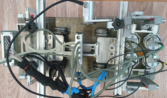
Photo 1. A scanner with a thinned antenna array, single-element inclined transducers, a path sensor and a contact fluid supply system (top view).
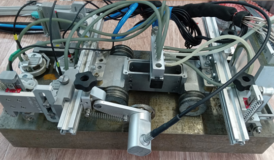
Photo 2. A scanner with a thinned antenna array, single-element inclined transducers, a path sensor and a contact fluid supply system (side view).
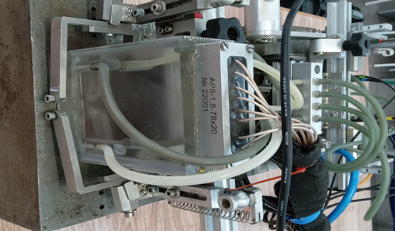
Photo 3. A thinned antenna array on a prism made of thermal material.
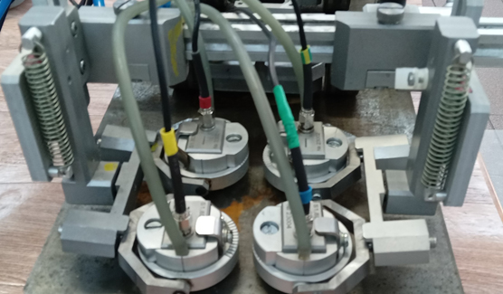
Photo 4. Single-element inclined transducers.
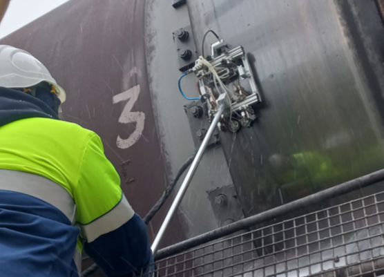
Фото 5. Сканер с рукояткой направления контроля, установленный на бандаже.
An AUGUR-ART ultrasonic flaw detector was used to carry out the inspection, [4] supporting the CFA technology. The flaw detector allows recording acoustic signals in the form of A-scans at the required speed. The captured A-scans are processed during in-house processing using UFA-2D technology in the AUGUR Analysis program.
The scanning scheme used a thinned antenna array (PRAR) with 8 elements with an aperture size of 78x20 mm, a central frequency of 1.6 MHz, mounted on a straight prism (angle 0 °) and four separate inclined transducers with an input angle of 42° and a central frequency of 2 MHz.
The scanning scheme is shown in Figure 1.
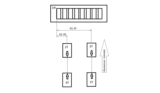
Figure 1. Scan diagram. The channel numbers and the direction of sounding are indicated (N – vertical T – transverse) 1N – "ПРАР" on the prism 0°; 2T..5T is a probe with an input angle of 42° in the direction of backward or forward rotation.
During the operation of the furnace, the scanning was carried out in two installations: a thinned antenna array and two pairs of converters separately. The scanning step is limited by the speed of rotation of the furnace at the time of inspection and the prevention of missing signals during scanning and was 4-5 mm. For one revolution of the bandage, there are about 5 thousand complete cycles of radiation and reception of 8 channels of RAR or 2 channels of piezoelectric probes. The step between the passages along the axis of the bandage is determined by the size of the "ПРАР" aperture and is 60-90 mm. Process water is used to ensure acoustic contact.
The sensitivity of the "ПРАР" channel was adjusted according to a tuning sample with flat–bottomed reflectors of Ø5 mm, the sensitivity of the piezoelectric probes channels was adjusted according to a sample with side reflectors of Ø3 mm.
The following coordinate system is used for acoustic images:- X, mm – counting along the surface of the bandage from the left edge (from the rising side);
- Y, mm – counting along the surface of the bandage against rotation;
- Z, mm – counting in depth from the surface of the bandage.
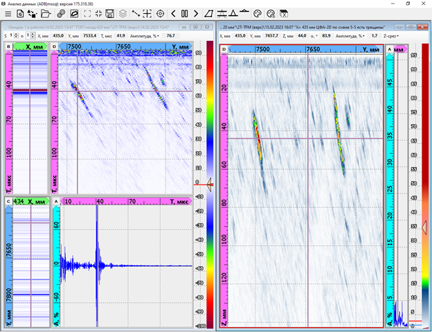
Typical results are shown in the figures:
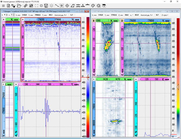
Figure 2. Results of inspection using AR (fragment). On the left is an A-scan of one of the AR reception channels (radiated the fourth element, received the fifth element), on the right is an acoustic image of the CFA-2D (signals of all elements). Two inclined cracks have been identified.
