Prisms for phased arrays
Ordering Information
When ordering a prism, specify the marking according to the marking system or the article of the prism from the list with examples.
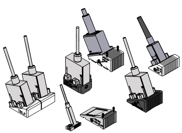
Marking system for ordering prisms

(when ordering a different type of attachment, attach a drawing of the required fit of the converter on the prism)
- X-32 - mounts for Sonatest OM-A1 converters - mounts for Olympus type A converters
- The angle of inclination of the prism 35 = 35°
- Location of the converter on the prism 0 = 0°
- 90 = 90° (for narrow for transverse defects)
- The outer diameter of the pipeline is indicated (mm] 273 = Ø273 mm
- O - glass organic (sound velocity 2.66 mm/mks) R - rexolite 1422 (sound velocity 2.35 mm/mks)
- I - fittings for the supply of contact fluid
- Lxx - prism length (mm)
- Hx - prism height (mm)
- Wxx - prism width (mm)
- P - protectors (in the form of pins)
- TRL - TRL circuit
Examples of prisms with technical parameters and dimensions
| ID | Article |
| ОМ-А10-31-R-IL34V | W0220001 |
| OM-A32-0-R-Н40 | W0220002 |
| OM-A12-0-R-Н40 | W0220003 |
| ОМ-А1х2-36-90-325-R | W0220004 |
|
ОМ-А1х2-36-20-90-325-R |
W0220008 |
|
ОМ-А11х2-36-90-325-R |
W0220009 |
|
ОМ-А11х2-36-20-90-325-R |
W0220010 |
| OM-A12-36-R-IL62V | W0220005 |
| OM-A11-36-R–IL37V | W0220006 |
| OM-A11-0-R-Н40 | W0220007 |
| OM-A1-31-R-IL30W30V | W0160008 |
| OM-A1-39-R-L32 | W0160010 |
| OM-A1-39-57-R-L32 | W0160033 |
| OM-A1-39-76-R-L32 | W0160034 |
| OM-A1-39-89-R-L32 | W0160035 |
| OM-A1-39-108-R-L32 | W0160036 |
| OM-A1-39-133-R-L33 | W0160018 |
| OM-A1-39-159-R-L32 | W0160011 |
| OM-A1-39-219-R-L32 | W0160012 |
| OM-A1-39-273-R-L32 | W0160019 |
| OM-A1-39-325-R-L32 | W0160037 |
| OM-A1-39-377-R-L32 | W0160020 |
| OM-A1-39-426-R-L32 | W0160038 |
| X-32-0-R-H40 | W0160039 |
| X-32-39-R-IL42 | W0160040 |
| X32-31-R-IML52V | W0160050 |
| X32-20-426-IML42V | W0160058 |
| X32-35-R-IML42V | W0160049 |
| X32-35-219-R-IРML52 | W0160062 |
| X32-35-245-R-IРML52 | W0160061 |
| X32-35-273-R-IРML52 | W0160059 |
| X32-35-219-90-R-IРML52 | W0160064 |
| X32-35-245-90-R-IРML52 | W0160061 |
| X32-35-273-90-R- IРML52 | W0160060 |
| Призма для преобразователей на фазированных решетках 5L32-A11 | W0160065 |
| Призма для преобразователя на фазированных решетках Olympus 5L32-A11 | ОМ-А11-0-Н25 |
| OM-A1-0-R | W0210001 |
| SA2-NS55S | W0210002 |
| OM-A2-0-R | W0210003 |
Features of fasteners
Fasteners of type OMA 1 (mm)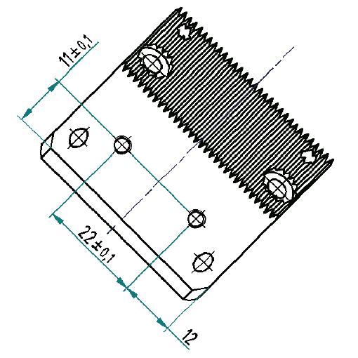
|
Fasteners type X-32 (mm) 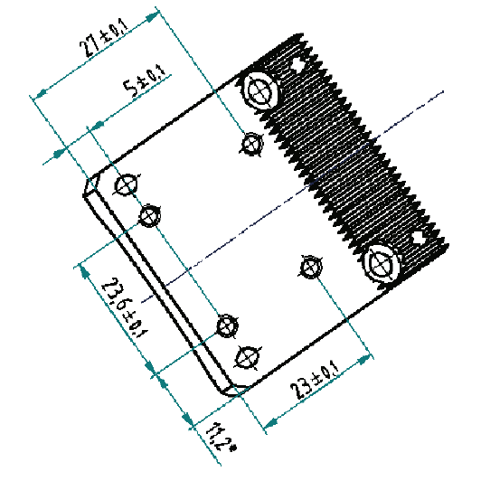
|
| ID |
Article |
| ОМ-А10-31-R-IL34V | W0220001 |
| OM-A32-0-R-Н40 | W0220002 |
| OM-A12-0-R-Н40 | W0220003 |
| ОМ-А1х2-36-90-325-R | W0220004 |
|
ОМ-А1х2-36-20-90-325-R |
W0220008 |
|
ОМ-А11х2-36-90-325-R |
W0220009 |
|
ОМ-А11х2-36-20-90-325-R |
W0220010 |
| OM-A12-36-R-IL62V | W0220005 |
| OM-A11-36-R–IL37V | W0220006 |
| OM-A11-0-R-Н40 | W0220007 |
| OM-A1-31-R-IL30W30V | W0160008 |
| OM-A1-39-R-L32 | W0160010 |
| OM-A1-39-57-R-L32 | W0160033 |
| OM-A1-39-76-R-L32 | W0160034 |
| OM-A1-39-89-R-L32 | W0160035 |
| OM-A1-39-108-R-L32 | W0160036 |
| OM-A1-39-133-R-L33 | W0160018 |
| OM-A1-39-159-R-L32 | W0160011 |
| OM-A1-39-219-R-L32 | W0160012 |
| OM-A1-39-273-R-L32 | W0160019 |
| OM-A1-39-325-R-L32 | W0160037 |
| OM-A1-39-377-R-L32 | W0160020 |
| OM-A1-39-426-R-L32 | W0160038 |
| X-32-0-R-H40 | W0160039 |
| X-32-39-R-IL42 | W0160040 |
| X32-31-R-IML52V | W0160050 |
| X32-20-426-IML42V | W0160058 |
| X32-35-R-IML42V | W0160049 |
| X32-35-219-R-IРML52 | W0160062 |
| X32-35-245-R-IРML52 | W0160061 |
| X32-35-273-R-IРML52 | W0160059 |
| X32-35-219-90-R-IРML52 | W0160064 |
| X32-35-245-90-R-IРML52 | W0160061 |
| X32-35-273-90-R- IРML52 | W0160060 |
| Prism for phased array converters 5L32-A11 | W0160065 |
| Prism for a phased array converter Olympus 5L32-A11 | ОМ-А11-0-Н25 |
| OM-A1-0-R | W0210001 |
| SA2-NS55S | W0210002 |
| OM-A2-0-R | W0210003 |
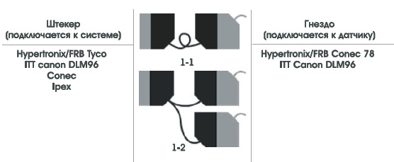
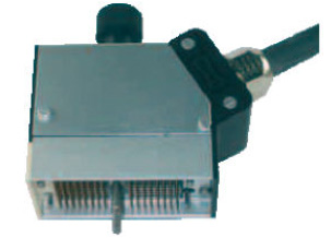 Hypertronix/FRB |
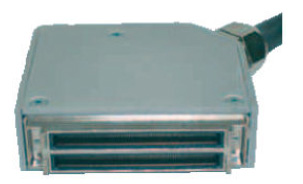 Tyco TCZ |
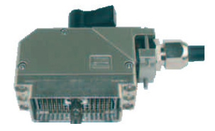 ITT Canon DLM96 |
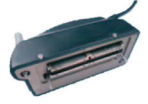 Ipex |
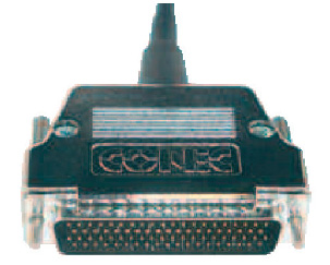 Conec 78 |
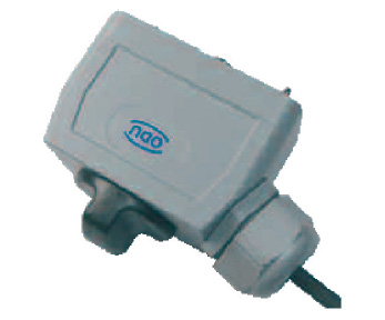 ODU |
Cable Specofocations
- Small losses due to attenuation or filtering of the signal.
- Good flexibility.
- Good mechanical stability during operation.
- The possibility of use in a variety of industrial environments.
Multi-coaxial cable with a total shielding of 50 ohms
| Number of channels | Until 16 | Until 64 | Until 128 | До 256 |
| Cable diameter | 4.1 mm | 5.6 mm | 7.8 mm | 8.7 mm |
| Minimum static bending diameter | 25 mm | 32 mm | 50 mm | 60 mm |
| Minimum dynamic bending diameter | 50 mm | 64 mm | 100 mm | 120 mm |
| Outer braid | Back PVC |
Black PVC or halogen-free PU |
Black PVC | Black PVC |
IMASONIC can offer several different cable protection options.
An additional protective cover can be installed in the connector.
Phased array sensors are compatible with most systems on the market. Various standard connector types are available, including: Hypertronix/FRB, Tyco, ITT Canon, Ipex, Conec, ODU and other.
In addition to sensors on phased arrays, IMASONIC can offer extension cords and adapters for connecting multiple sensors to a system, or a sensor to systems with different types of connectors.
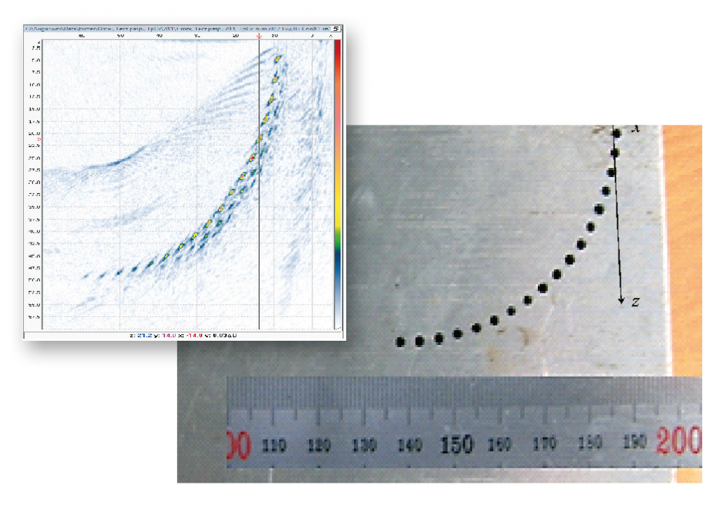
Digital focus across the entire inspection area
Full focus across the entire inspection area, not along the focus line. Improved image quality by increasing the signal-to-noise ratio. The restoration of defect images is performed by the C-SAFT method, taking into account the effect of the transformation of wave types when reflected from the boundaries of the inspection object.
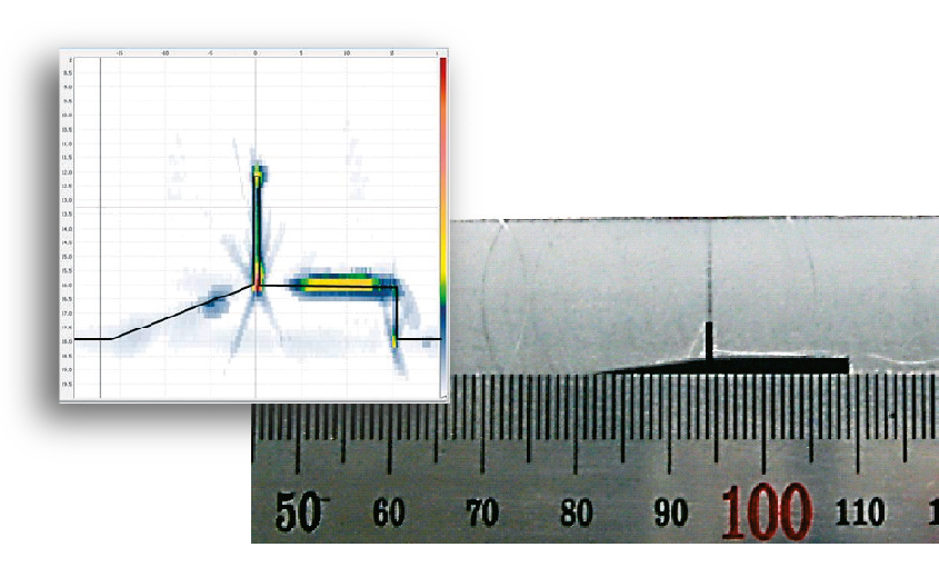
Getting an image of the defect boundaries
AUGUR-ART algorithms allow you to obtain B-type images, according to different acoustic schemes, taking into account the reflection from the bottom of the inspection object. After digital processing of these images, the task of obtaining information about the shape of the defect is facilitated.
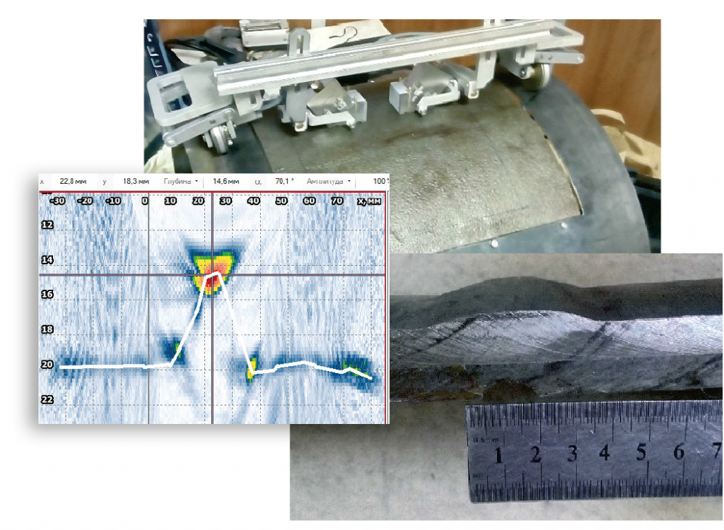
Restoration of the bottom surface profile
The technology allows measuring the thickness and speed of the ultrasonic wave in the inspection product in the area of the base metal and the welded joint, as well as taking into account the uneven external surface. The thickness measurement error in the range from 20 to 100 mm is not more than 1-2%. It is used in conjunction with digital antenna focusing technology.
Data analysis
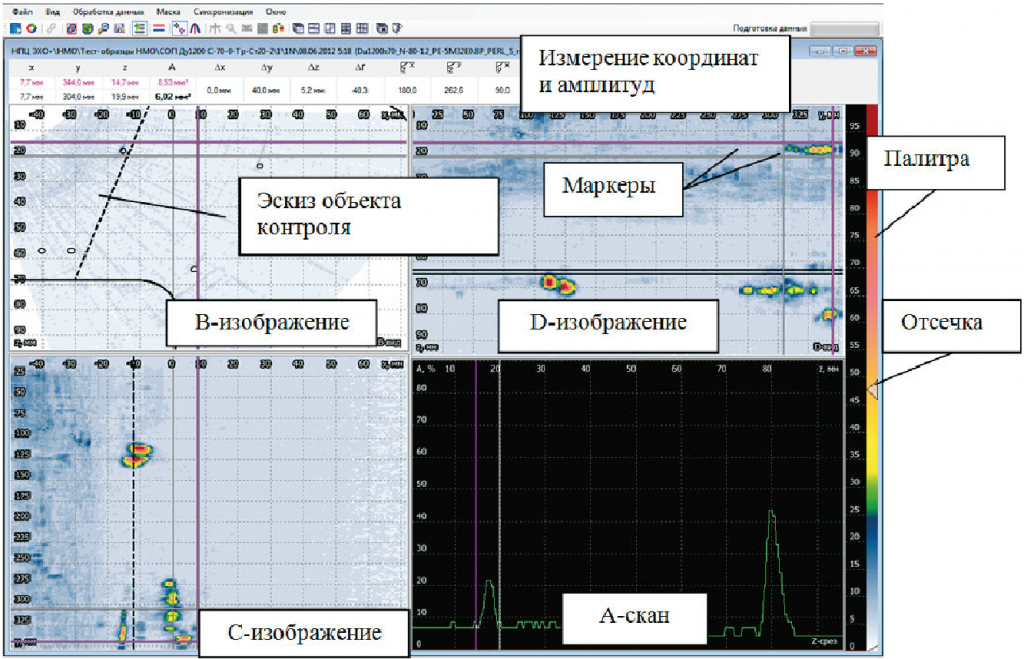
- A, B, C, D, S-scans
- Visualization taking into account the input angle
- Visualization in FR, SAFT, CFA, TOFD modes
- Compensation of the scanner backlash
- Creating sketches of inspection objects
- Changing the contrast and cutoff
- Sensitivity equalization (RF, RF)
- Measuring cursors
- Centralized database of inspection results and objects
- Import of inspection data from various formats
- Creating reports with inspection parameters and defect information
