Consideration of anisotropic properties of repair welding in pipelines DN800. Part I
Introduction
Practically any welded joint cannot be considered as a homogeneous isotropic medium for control by ultrasonic (ultrasonic) waves. If the phase changes during the propagation of the ultrasonic wave are less than 180 degrees, then the medium can be considered as isotropic and homogeneous. Otherwise, restoring the image of the reflectors using simple algorithms will cause the glare of the reflectors to shift from their true positions, and the shape of the glare will be distorted. Moreover, distortions can lead to the fact that instead of one glare, two or more with a smaller amplitude will appear. As a result, the glare amplitude of the large reflector may not reach the rejection level and the defect will be missed.
One of such objects is repair welding in welded joints of pipelines DN800, which have anisotropy. The situation is complicated by the presence of anticorrosive surfacing on the inner surface of the pipe, which also has pronounced anisotropic properties, which does not allow working on a single reflected beam, without taking into account its anisotropic properties.
Sample of repair welding in the pipe DN800
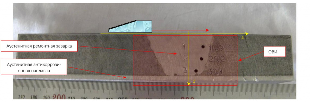
In the sample of the Dn800 pipeline with a thickness of 38 mm with austenitic repair welding, three lateral cylindrical holes with a diameter of 2.2 mm were drilled, numbered with numbers 1, 2, 3 stamped on the surface of the sample (Fig. 1). Antenna array (2.25 MHz, 20 elements, piezoelectric element size 1.1 ×10 mm, gap 0.1 mm) on a prism of 20 degrees moved along the surface of the sample across the weld in 39 positions with a step of 0.98 mm (triple scanning mode: combination of electronic and mechanical scanning). The scanning area along the front face of the prism is schematically shown in the figure below by a red arrow.

Fig. 1. Photo of a sample of the DN800 pipeline with austenitic repair welding (view from the end with three BTS). The red arrow schematically shows the scanning aperture
Figure 2 shows a photo of the sample from the opposite side, where two 2.2 mm diameter drill bits were drilled in the center of the welding. The scanning area along the front face of the prism is schematically shown in the figure below by a red arrow.

Fig. 2. Photo of a sample of the DN800 pipeline with austenitic repair welding (view from the end with two BTS). The red arrow schematically shows the scanning aperture
The principle of determining anisotropy
In these specific measurements, the types of reflectors and their location were known. It is assumed that the welding has cubic symmetry, that is, to calculate the delays of echo signals, it is necessary to determine only three elastic parameters. This allows you to restore the images of reflectors at different values of the elasticity coefficient and the angle of rotation of the crystal axes and select those parameters that allow you to get a focused image.
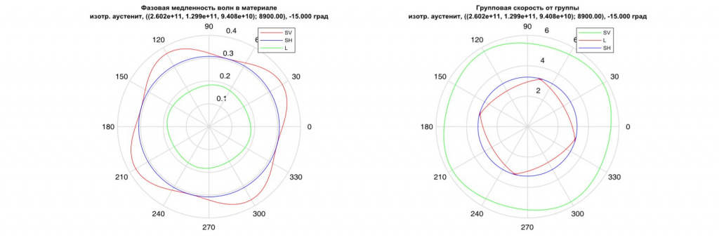
As a result of the above procedure, the elasticity coefficients for cubic anisotropy were determined as (2.602e+11, 1.299e+11, 9.408e+10) Pa, and the angle of rotation of the crystal axes was determined as -15 degrees. The average velocity of the longitudinal and transverse waves were equal to 5.574 and 3.058 mm/ms. Figure 3 shows the phase slowness and group velocities for the anisotropy parameters defined above.

Fig. 3. Phase slowness and group velocities for certain anisotropy parameters
Image of three BTS
Fig. 4a shows the CFA-X image reconstructed under the assumption that the medium is homogeneous, and Fig. 4b under the assumption that the welding has an anisotropy defined in the section The principle of determining anisotropy. The lines of the borders of the object of control and the BCO are drawn on the image with black lines. The glare of the boundaries of the BCO in Fig. 4b became more focused, and the glare of the bottom became even.

Fig. 4. CFA-X-image reconstructed under the assumption that: a) – the medium is homogeneous, b) – the welding has anisotropy
Image of two BTS
Figure 5a shows the CFA-X image reconstructed under the assumption that the medium is homogeneous, and Figure 5b under the assumption that the welding has anisotropy. The lines of the borders of the object of control and the BCO are drawn on the image with black lines. The glare of the lower BSO border in Fig. 5b is more focused and its amplitude has increased compared to the image in Fig. 5a. The glare of the bottom has become better consistent with the bottom of the sample.

Fig. 5. CFA-X-image reconstructed under the assumption that: a) – the medium is homogeneous, b) – the welding has anisotropy
Conclusions
It is quite simple to take into account the inhomogeneity and anisotropy of the control object – the problem is to determine in practice the welding dimensions and anisotropy parameters: its type, elasticity coefficients and rotation angles of the crystal axes.
This problem can be solved by echo signals measured according to a separate scheme by two antenna arrays installed on both sides relative to welding. An article was sent to Flaw Detection on the problem of determining three elasticity coefficients in a welded joint.
Bazulin E.G.