AUGUR TF
Modular system of automated ultrasonic control using phased arrays and the TOFD method
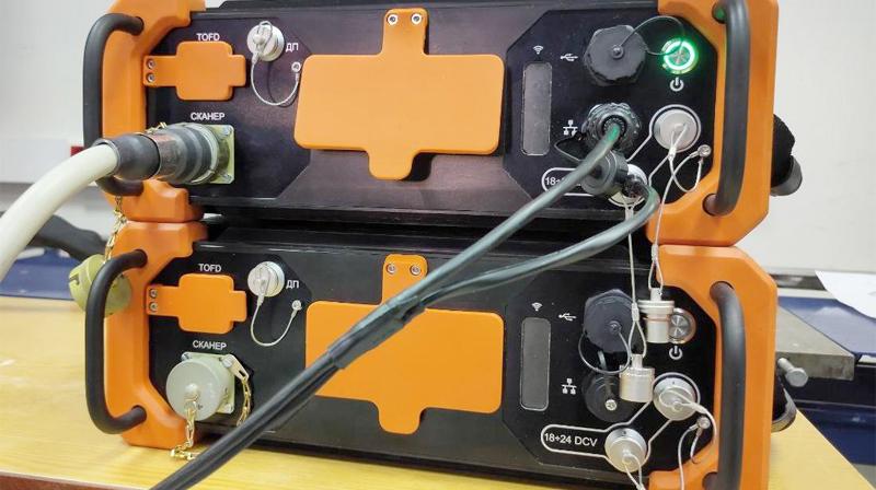
Modular AUGUR-TF system using phased arrays and the TOFD method. The system has been successfully tested at "GAZPROM".
Unique features of the AUGUR-TF modular system
Combining several control technologies in one modular AUGUR-TF system is an effective solution for automated ultrasonic inspection of welded joints, ensuring maximum return on ultrasound without loss of performance:
- FR-mode is an effective search for defects of various orientations along the entire seam section
- Zonal focusing — detection of defects along the edge of the welded joint (manual and automatic welding)
- TOFD-mode — additional information on diffraction echo signals from defects
- CFA mode — the most accurate visualization of defects, determination of the physical dimensions of defects
- AVIK-mode — the use of a laser profiler to measure the parameters of the weld
The AUGUR-TF system provides:
- 4 operating modes: phased array mode; TOFD mode; digital antenna focusing mode; zone focusing mode
- Detection and visualization of defects, determination of their sizes and coordinates
- Carrying out automated control of products and materials up to 500 mm thick
- Multifunctional program for registration and analysis of control results
- Module for calculating control parameters for the TOFD method and FR
- Replacement of radiography with ultrasound control
- Integration with the laser meter of the weld surface profile
Standard equipment*
- AUGUR-ART FR (art. D0160007)
- Scanner on magnetic wheels SK.TF.M
- Automated Visual Inspection Module
- Set of prisms PEP, TOFD, FR
- Connecting cables
- Power cable (220V)
- Control computer
- Packaging

Ultrasonic inspection of welded joints in the FR mode
- Calibration of RF/RF and angle sensitivity
- Calibration of the delay in the prism
- Calculation of focusing laws by depth, by displacement, by radius
- Focusing laws are calculated by the device without importing from a computer
- High data collection performance
- Combination of different methods using several groups of converters in one pass, which increases the control performance
- Creating a sketch of the control object and applying a sketch to the data make it easier to identify and measure defects
- Compatible with scanners from various manufacturers
- Saving control data for subsequent analysis

Ultrasonic inspection of welded joints in TOFD mode
- High control sensitivity
- Independence of defect detection from its orientation
- High control performance due to the control of the entire volume of the welded joint in one pass
- Saving control results for subsequent analysis
- Depth gauge calibration
- Calculation of control parameters using a specialized program “UZ calculator”
- Conclusions based on the results can be configured and issued automatically
- Compatible with scanners from various manufacturers

Ultrasonic inspection of welded joints in the CFA mode
- Digital antenna focusing (UFA) in real time and in the form of post-processing
- The ability to evaluate equivalent reflectivity
- Measurements of the length, height and coordinates of defects with high resolution
- Maximum possibility of classification of defects
- Application of various processing algorithms by the CFA method for control objects of increased complexity
- Obtaining high-quality images to increase the reliability of control results
")
Automated Visual Control (AVC) mode
With the use of a laser profilometer, the parameters of the weld are measured: the width and height of the roller, the displacement of the edges, the depth of the intervalic sinking, the length and height of the undercuts.

EN Automated ultrasonic monitoring in TOFD+HEADLIGHT mode
In the main mode, the inspection of welded joints is carried out by antenna arrays located on both sides of the welded joint and operating in sector scanning mode by focusing along the boundary of the fusion of the deposited metal of the welded joint and the base metal. For reliable detection and measurement of vertical planar defects, TOFD inspection is used in conjunction with the headlight mode.

Accounting for anisotropy
The sample is 37 mm thick with repair welding and five side drilling holes with a diameter of 2.2 mm. Due to the consideration of anisotropy in the welding, the glare focusing has noticeably improved and the glare has become more accurate to correspond to the actual position of the boundaries of the holes and the bottom of the sample.

Multi-CFA Mode
In the Multi-CFA mode, the data obtained are processed using the C-SAFT algorithm to obtain an image of discontinuities. The visualization of discontinuities is performed when the inspection data is presented as a raster picture of the distribution of amplitudes in the set color palette. When visualizing discontinuities, the presence of reflections from the inner and outer surfaces of the inspection object with a given shape, wave type transformations are taken into account, images obtained using several inspection schemes are combined in one image.

Software
AUGUR software installed on the control computer controls the operation; data collection, storage and processing using the C-SAFT algorithm; calculation of focusing laws, data visualization; provides functions for data analysis and automation of the inspection protocol. The flaw detector software package includes 3 main program blocks: Data logging, Data Analysis, ultrasonic calculator. The Data Logging program is used to configure control parameters, control scanners, and record initial control data into a common system database. The Data Analysis program is for processing control data from a database, visualizing images of discontinuities, analyzing inspection results and preparing a final conclusion based on inspection results. The UZ calculator program is for calculating the focusing laws of antenna arrays, taking into account the geometry of the welded joint, as well as for calculating the control parameters by the TOFD method.
Specifications
| Number of channels | 64; 128 pcs |
|
The range of setting the amplitudes of the excitation pulses |
от 30 до 100 В с шагом 1 |
|
Permissible deviation of the setting of the amplitude of the excitation pulses |
±10 % |
|
The range of setting the duration of the excitation pulses |
from 50 to 400 ns |
|
Permissible deviation of the setting of the duration of the excitation pulses |
±10 % |
|
The range of adjustment of the gain of the receiving path |
from 0 to 80 дБ |
| Gain adjustment step | up to 0,5 дБ |
| Limits of the permissible absolute error of measuring the ratio of signal amplitudes at the receiver input | ±1 дБ |
|
The range of adjustment of the duration of the sweep |
from 1 to 600 μs |
|
The range of adjustment of the sweep delay (at a signal digitization frequency of 20 MHz) |
from 1 to 200 μs |
|
The range of measuring the depth of the defect |
from 1 to 200 mm |
| Maximum thickness of controlled objects | 500 mm |
|
|
±0,8 mm |
|
|
±(0,3+0,03*z) mm, z - depth value, mm |
| The absolute error of measuring the distance from the point of entry of ultrasonic vibrations to the projection of the defect on the surface, provided that the value of the aperture angle * a, related to the length of the ultrasonic wave λ is at least 5 degrees / mm; | ±1,0 mm |
| The absolute error of measuring the distance from the point of entry of ultrasonic vibrations to the projection of the defect on the surface, provided that the value of the aperture angle * a, related to the length of the ultrasonic wave λ is less than 5 degrees / mm | ±(0,3+0,03*z) mm, z - distance from the insertion point to the defect projection, mm |
| The measurement range of the distance traveled by the path sensor | from 1 to 20000 mm |
| The relative error of measuring the distance traveled by the put sensor in the range from 1 to 100 mm | ±0,5 % |
|
Relative error of measurement of the distance traveled by the sensor of the put in the range from 100 to 20000 mm |
±0,5 % |
|
Overall dimensions of the system unit (length x width x height) |
up to 400 х 300 х150 mm |
|
Weight of the system unit |
up to 9 kg |
| Average service life | from 10 year |
|
The power is supplied from an external DC power source (from a rechargeable battery or a power supply connected to an AC network) with a rated voltage |
24 V |
|
Operating conditions at ambient temperature |
from +1 to +40 °С |
| Operating conditions at relative humidity, at a temperature of +25 ° C | from 15 to 80 % |
|
Operating conditions at atmospheric pressure |
from 630 to 800 mm of mercury column |